A signal generator made for controlling a dual conversion HF front-end and for making IP3 measurements. Here are some specs:
- Generates two sine waves. One for each SMA port.
- Frequency range from 500 KHz up to 150 MHz.
- Power from -99 dBm to -5 dBm.
- Controls for setting up two tone measurements.
- Controls for tuning a dual conversion HF front-end.
- That’s it.
The generator is made up of a bunch of stuff I’ve been playing with. There are two AD9951 DDS chips for synthesizing signals (see below). There is a 300 MHz Atmel M7 chip on a board my dad and I built last year. The display is a 3.5″ Enhanced Nextion screen. And everything else I bought on Amazon or eBay.

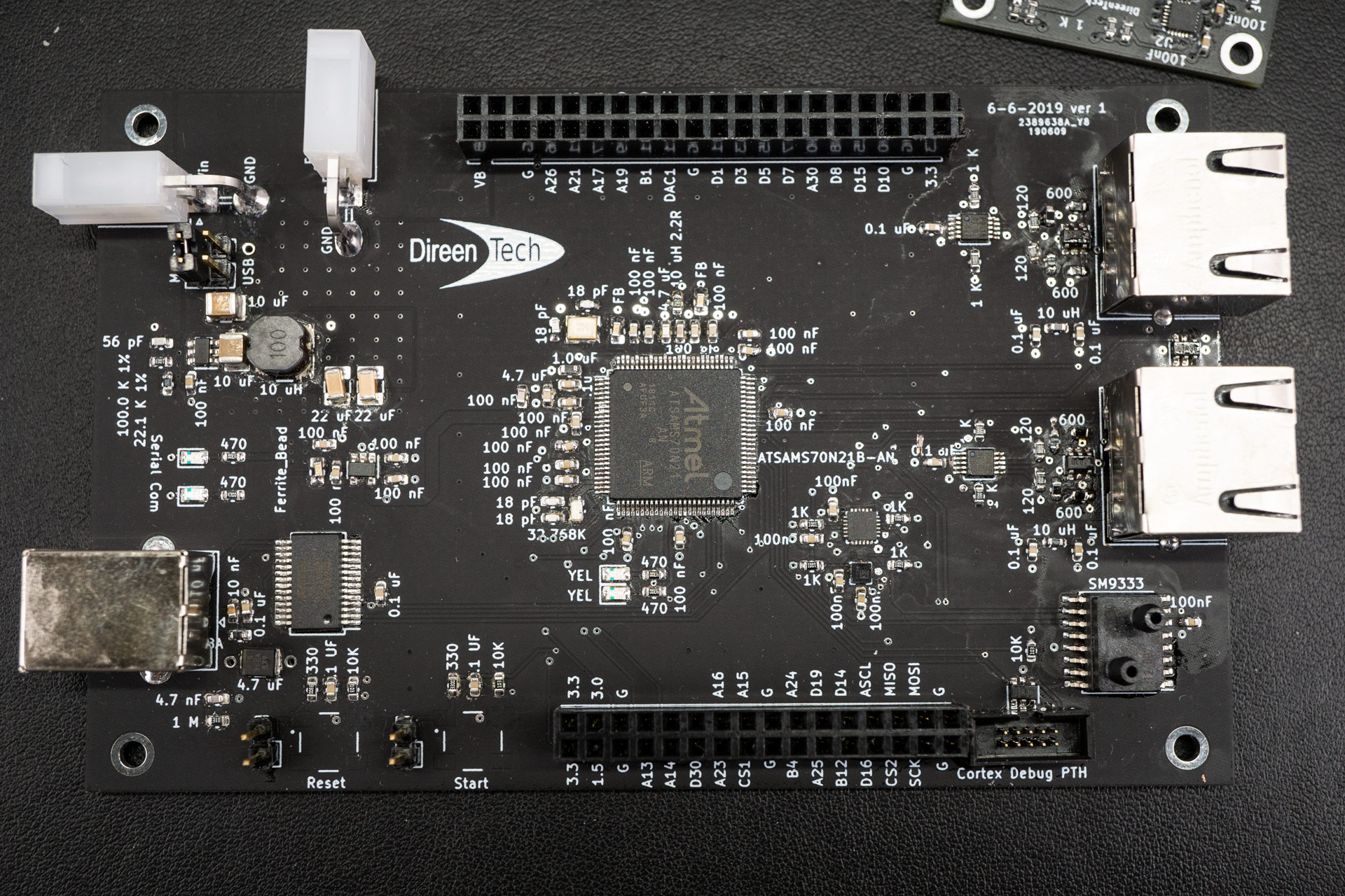
Here is the control board containing the Atmel SAMS70 chip. You may notice the poor soldering job. This is because I did it myself. We designed the board for a variety of projects, which is why there are a couple ports for hats we can add onto the board. This board has been a lot of fun to develop.
Below is a picture of the control board and the AD9951s placed within a cheap metal box from Amazon. The aluminum box on the right containing the DDS modules was also bought on Amazon. I really like these little boxes for RF projects. Unfortunately, I didn’t put any filter on the ports of the DDS circuit boards so noise creeps out onto the ribbon cable 😐
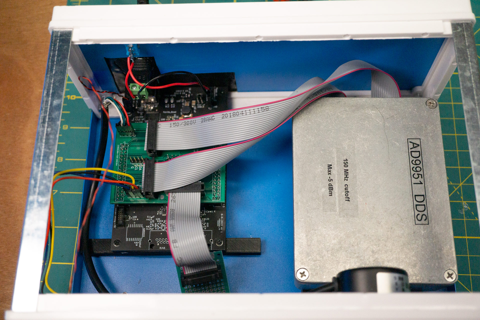
Inside the aluminum box I screwed the DDS modules into 3D printed stands that are glued to the aluminum bottom. This makes it easy to get the modules in and out for servicing.

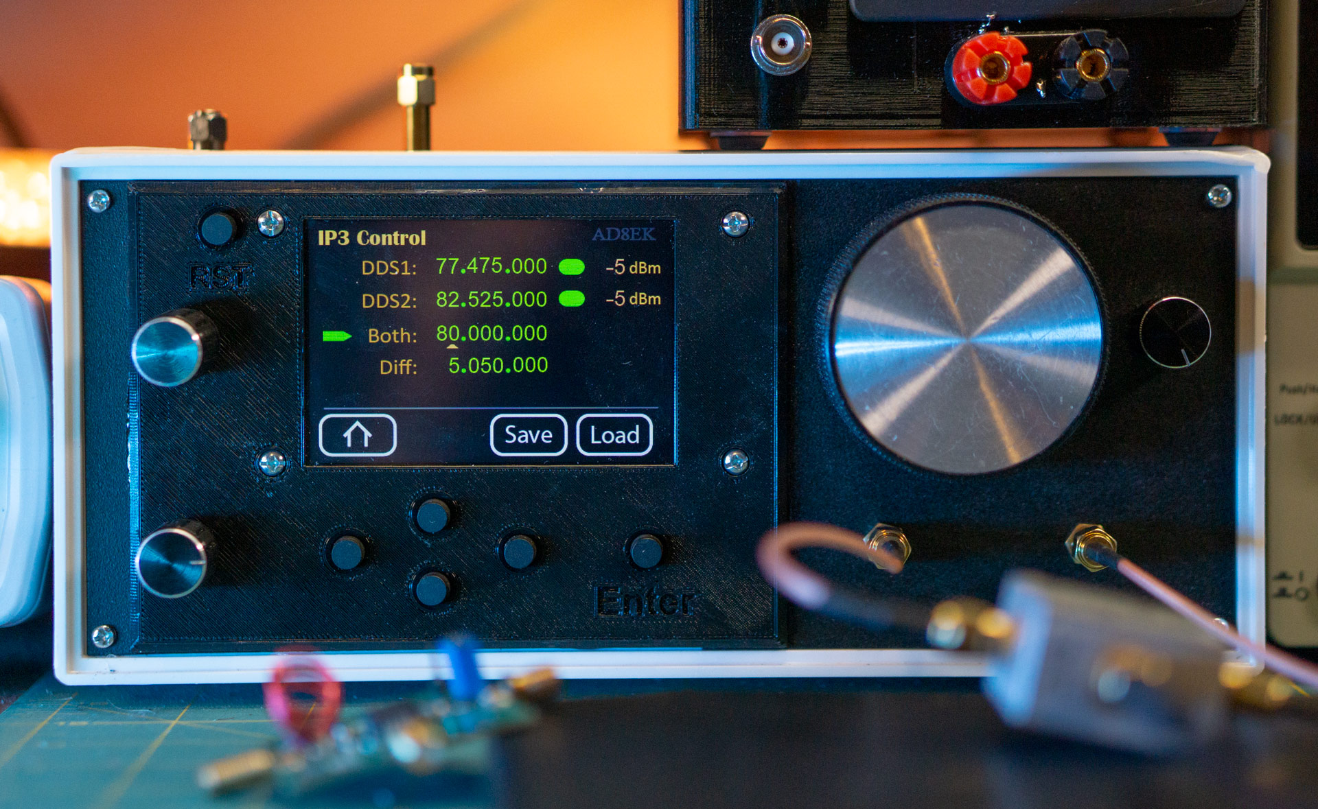
If you haven’t used a Nextion display in one of your projects yet, DO IT. It’s the easiest way to make a nice looking users interface (touch included) without having to write a mountain of code. The reason my display doesn’t look good (see below) is that my brother didn’t help. You can get an idea of how it should have looked if you visit his blog within this domain (http://www.direenworks.com). The particular Nextion display I used was a 3.5″ Enhanced version found on Amazon. I 3D printed a holder for it, some buttons, and rotary encoders, which was a lot easier and cleaner to do than just cutting places within the cheap metal box.
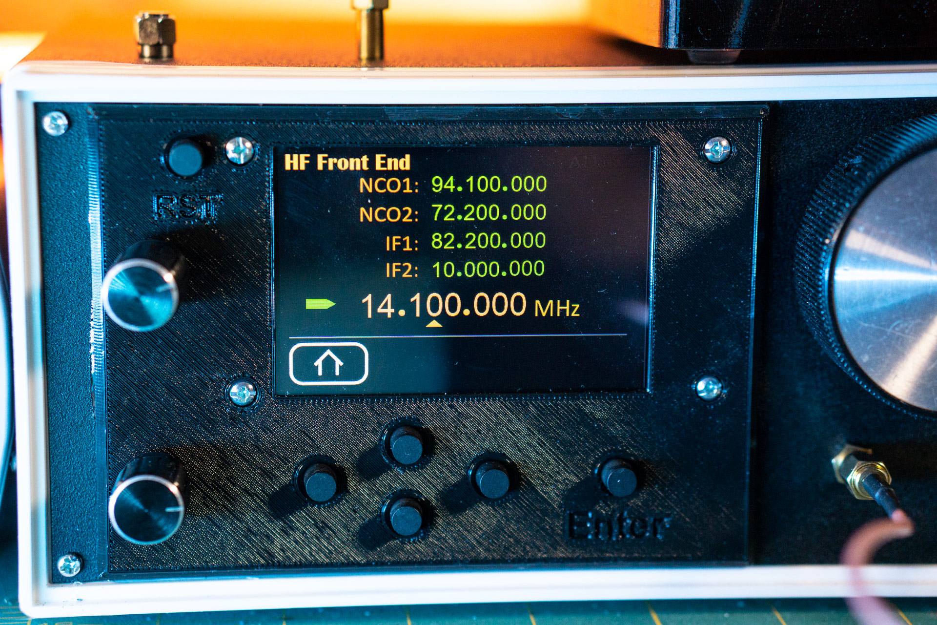
I made two pages for the display. The page shown above is for controlling an HF front-end. The first NCO1 frequency is used to mix a signal up to a first IF and the second NCO2 is used to mix down to a second IF. The frequency at the bottom is the tuned frequency I’m interested in. I wanted this level of control so that I could play with different IF frequencies.
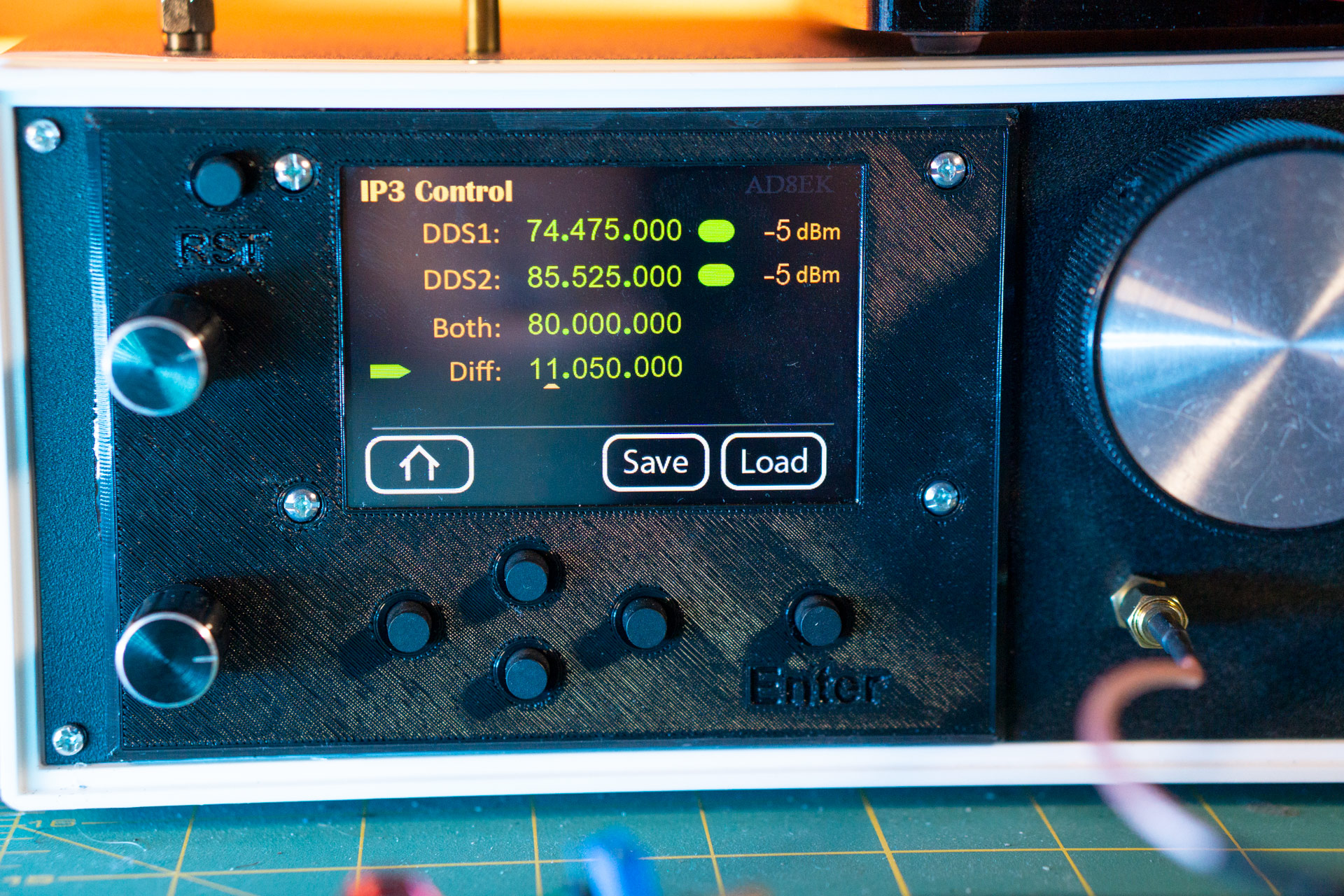
The second page is for controlling two tones at a time (see below). This is useful for IP3 measurements (measuring linearity of devices). The two DDS can be controlled independently or together and I can control their output power.
Here is a picture of the signal generator being used to measure OIP3. The device under test is a PGA-103 gain block and I measured OIP3 to be 34 dB. This was nice, because that’s what the datasheet said it should be. The controls of the signal generator make it really easy to choose frequencies I’m interested in and scrub through a reasonable amount of power levels.

I’m happy with this project. I now have a nice tool for generating a couple frequencies in the HF and VHF bands. I’m not sure if it was the most economical route to get what I wanted. I think all in all I spend between $250 and $350 to make it. But, I wanted to develop these pieces so I can use them in other radio projects. Fun stuff.
If you made it all the way to the bottom of this post, thanks for hanging out!
73