This post is about testing the RF measurement bench I’ve been making. I now have a DIY kit to make noise figure measurements, and a DIY signal generator to make TOI measurements. These along with my KC901V Chinese network analyzer and my Siglent spectrum analyzer provided me with a lot of DIY power.
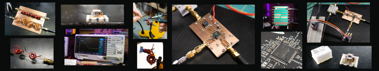
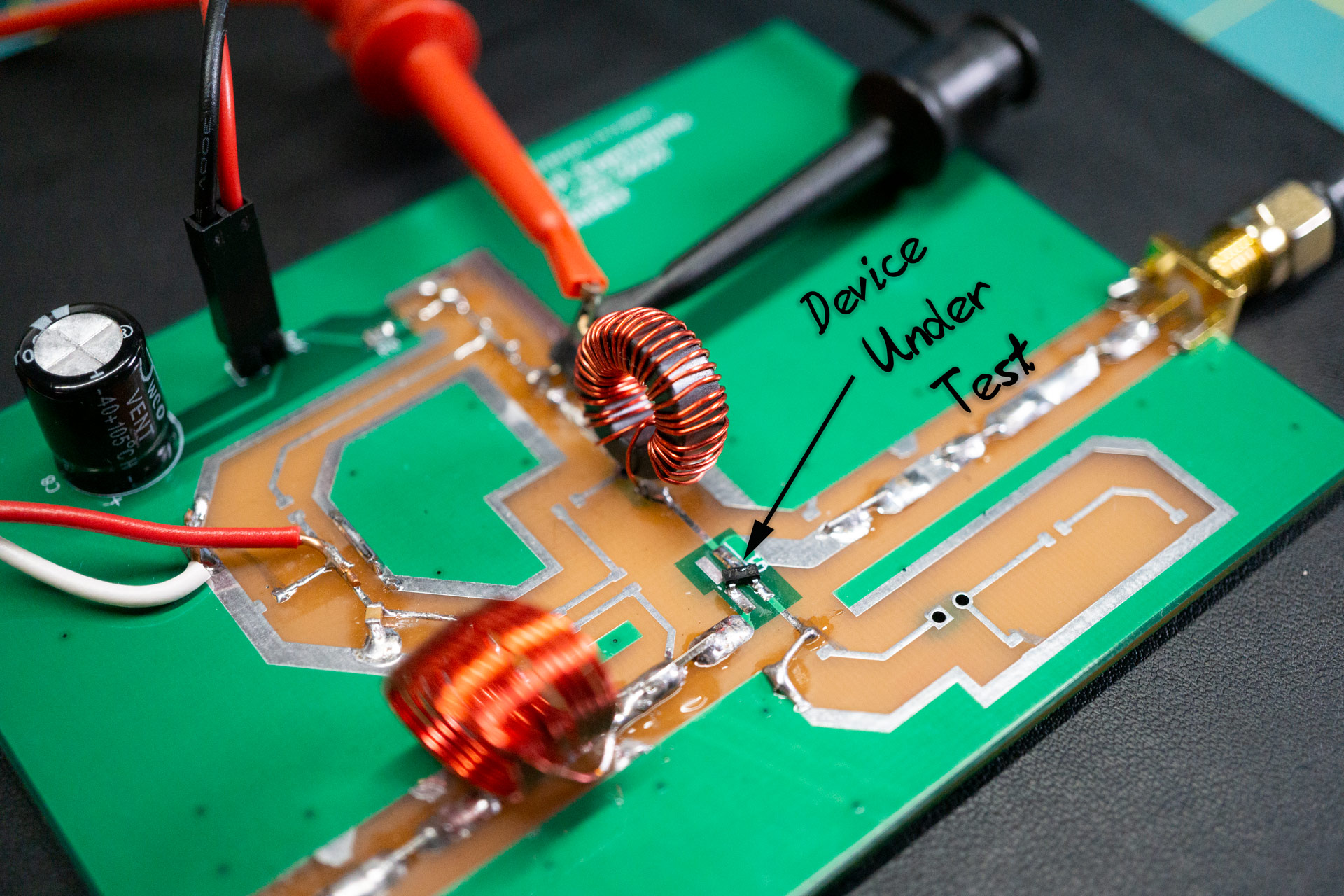
The image above is a board I had made to test common emitter amplifier configurations. It has room for biasing components, degeneration components, a few places for matching components and exposed metal where I can solder in anything else I want. I made 10 of these for about $30 (ordered from JLCPCB). I have a booklet of 0805 resistors and capacitors I bought off of Amazon, as well as a bunch of wire for making inductors.
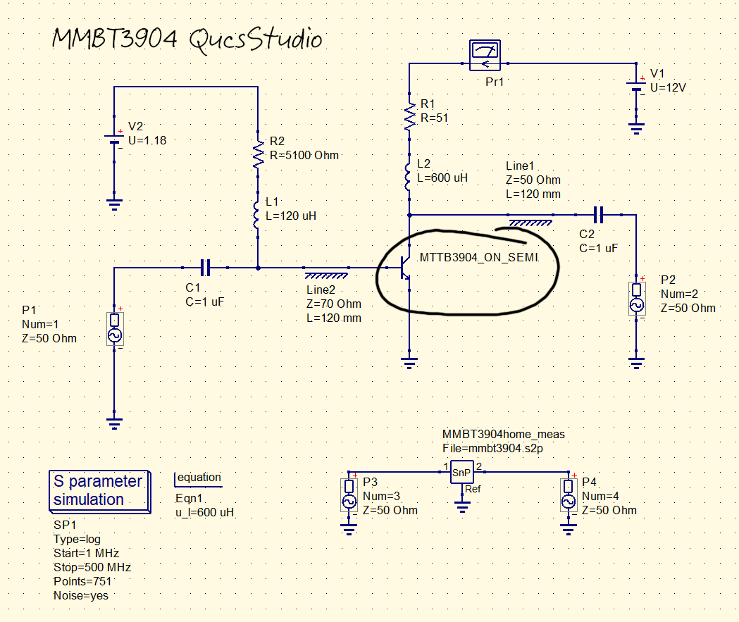
The device I tested is a MMBT3904. No matching, no feedback, no degeneration. Just a couple bias tees and transmission lines. The QucsStudio design shown above provides the values I used for the experiment. I used V2 to test a couple biasing points (20ish mA and 40ish mA).
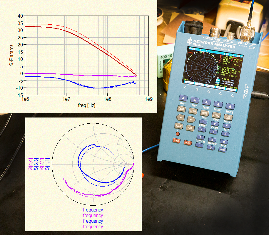
I used my KC901V Chinese network analyzer to measure the S-Parameters and then compared them with simulated results. The thick lines in the plots above are the measurements, and the thin are simulated with QucsStudio. I had to alter RB and CJC in the MMBT3904 Spice model to get the measurement to line up with simulation. Doing so made things line up nicely, but I’m not sure it exactly corresponds with what’s going on. Since I’m just playing, I didn’t spend too much time thinking about it. Good enough for who it’s for.
Next I measured noise figure. The setup seen below is the kit I built for measuring noise with my Siglent spectrum analyzer. At the bottom of the image you see the calibrated noise source from RF Design. It has an ENR of 15 dB and is calibrated from 10 MHz to 1420 MHz. The top of the screen shows a box containing a 25 dBish LNA to set the noise floor and add some gain going into the spectrum analyzer.
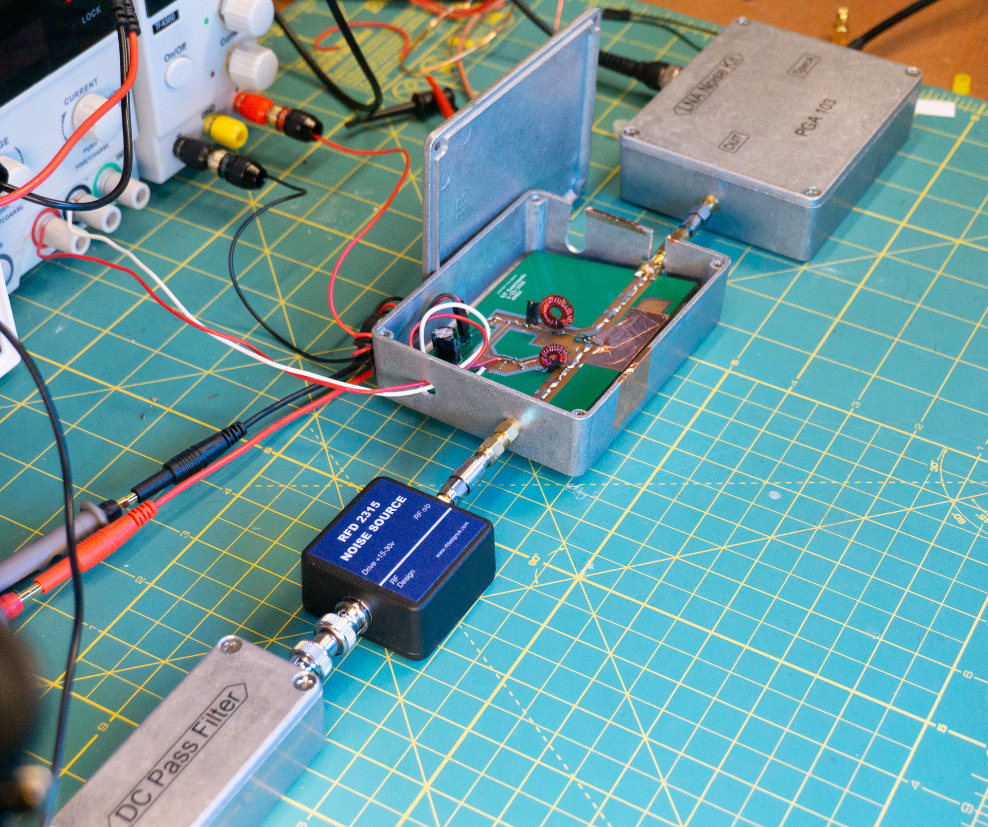
When I made the common emitter circuit board, I designed it so I could easily stuff it into the aluminum box shown above. I buy these from Amazon and like to use them for RF project boxes. For noise figure measurements you really need to do something like this; otherwise, environmental noise easily corrupts the measurement.
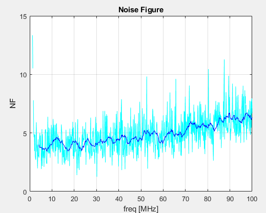
For the measurement I use MATLAB to control the spectrum analyzer. MATLAB places the analyzer into the correct state and collects data over the limits I specify. Using the ENR of the noise source, I calculate noise figure via the Y-Factor method. I’ve had to spend time getting this right, but I believe the figure above is correct to within 1 dB… or two. There are many places where uncertainties creep into these measurements and I’m still working on understanding the limits of this setup. But, the datasheet for the MMBT3904 does say its noise figure is 5 dB. It does not specify the minimum NF, so I’m not sure how small it can be. (Stay tuned in future posts where I make a noise figure parameters measurement DIY kit 😐 .)
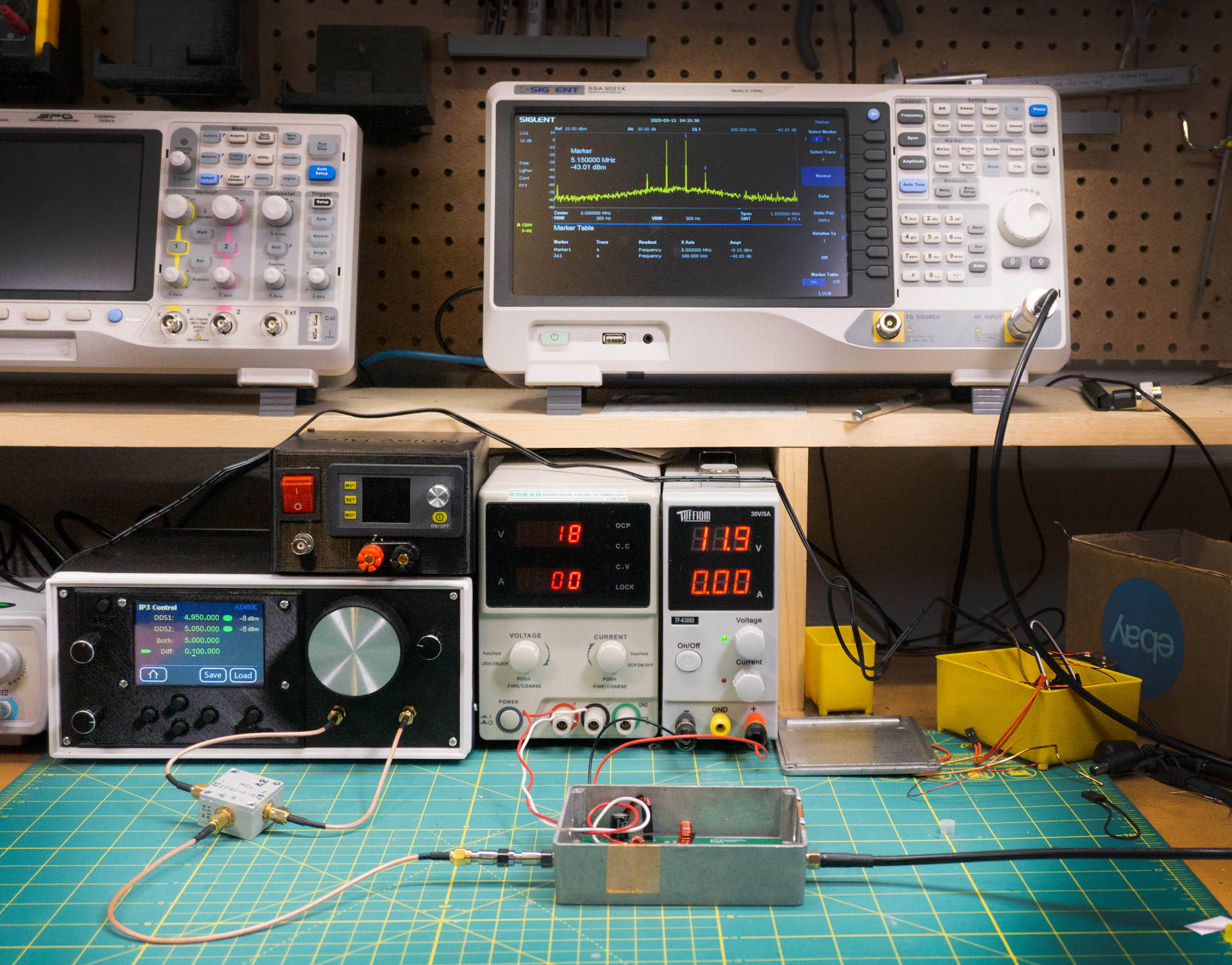
The final measurement I made was of the TOI using my new signal generator. I built this box and wrote about it in a previous post. The box can be seen in the lower left side of the image below. I made it so I could easily generate a couple tones for doing IP3 measurements. (It also does other stuff.)
The OIP3 value I measured was about 21 dB. To verify, I used Harmonic Balance analysis in QucsStudio:
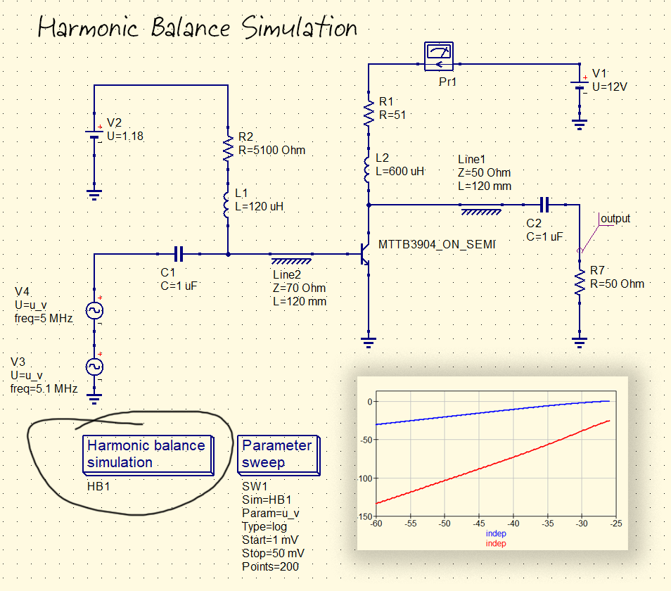
Aaaand the result is OIP3 = 20.9 dB. Usually when simulation and measurement are this close I’m more suspicious than if the results were wildly off. But, since this was just an exercise in testing out my RF measurement bench, I’m going to call it a day.
Right now I’m really happy with this setup. I’ll continue ironing out problems and reducing uncertainties as I work on more projects.
73,
AD8EK