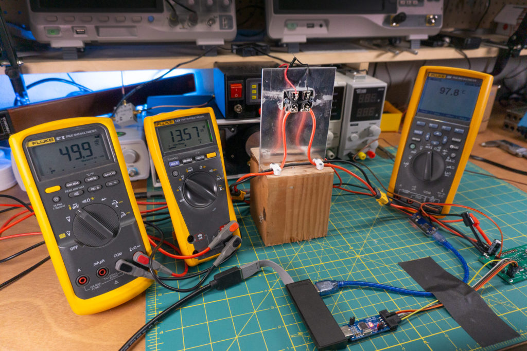
I built an electronic speed controller (ESC) and I’m in the process of setting up a bench to measure it. This post has a few pictures of my setup and a little description of my ESC.
The above image answers the question: Do I have enough Fluke meters? No, I need more. From left to right they measure
- Current into the ESC
- Voltage applied to the ESC
- Temperature of the N-Channel MOSFETs
Here is the demo ESC board I designed and soldered together
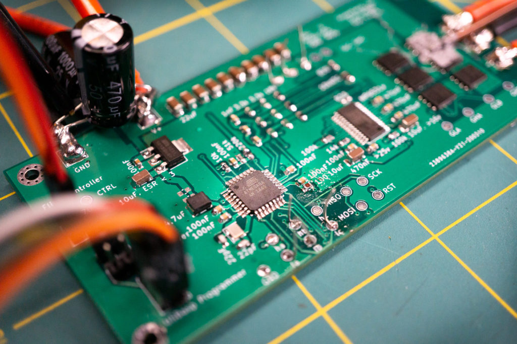
If you know quadcopters, or other multirotor UAVs, you’ll notice this design is huge. It will get smaller in the next rev, but I wanted a board with a bunch of test points and additional components. This way I can balance everything out before I make things smaller.
The MOSFETs are Infineon BSC027N06LS5s. I spent some time looking for low resistance, high current transistors for the project. Specifically, I wanted a high current rating without having to dip the transistors in liquid nitrogen. Infineon specifies that their transistors can handle 23 Amps in ambient conditions. I’ll have to do some tests to see what I can get out of them. I do plan on putting a heat sink on them, but I’ll play around with them a little in the air first.
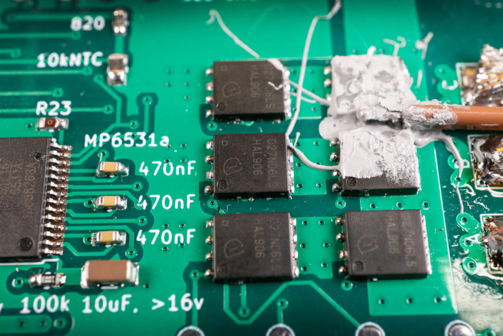
The goo you see in the upper right is slathered around my type-k temperature probe, which is connected to my Fluke 289.
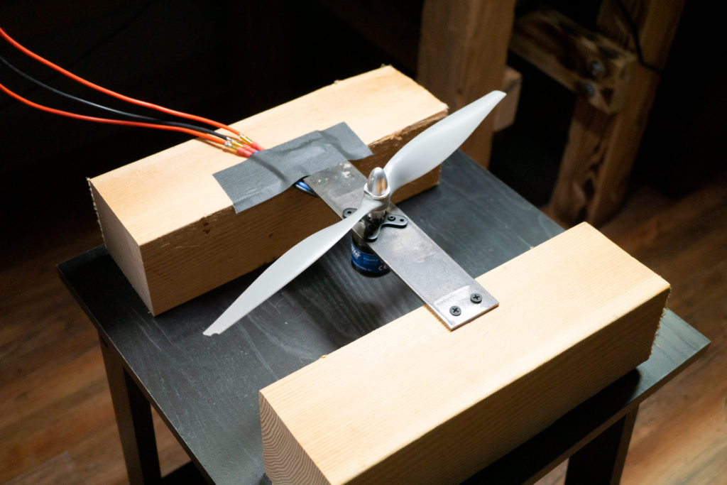
I don’t know much about motors so I went to the hobby store and found something that looked fairly stout. I wanted a setup that would pull on the transistors pretty hard. The image below is of the E-flight EFLM4025C with a 14″ blade attached. I don’t think you would usually use these in a multirotor.
Initial tests wore out my 5 Amp power supply quickly. I anticipated it would, so I bought a couple 30 Amp power supplies on Amazon a couple days ago. What I didn’t realize is that the motor would draw so much current at the lowest throttle setting. Right out of the gate it maxed out my little power supply.
I can’t measure much above 10 Amps directly with my Fluke meters so I bought a sense resistor. The image below shows the resistor attached to a heat sink.
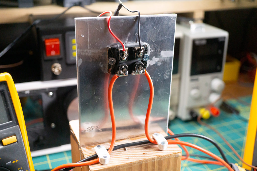
I cut the heat sink and epoxied it to a block of wood. I figured I could use a fan if it started getting too hot. What I forgot though, is that I bought a 0.01 ohm resistor and not a 0.1 ohm. I don’t think it’s gonna get too hot. So now it’s just art.
I’m using BLHeli on an Atmega8 to control the transistors because it’s open source: https://github.com/bitdump/BLHeli. I chose the Atmel processor instead of the SiLabs processor because I already have all the stuff for coding and programming the Atmega8s. I code using Atmel Studio and programming was done using a USBasp dongle. I’ve had to change a few lines of BLHeli code to configure the chip, but it was easy because of the great job those guys did on the code.
If you are interested in making your own ESC there are a few great places to learn. Especially this first reference, which comes from a guy that really seems to like making ESCs:
- Guy loves ESCs: https://www.rcgroups.com/forums/member.php?u=696658
- Programming with BLHeliSuite: https://www.rcgroups.com/forums/showthread.php?2136895-BLHeli-for-Atmel-and-Silabs-united-by-BLHeliSuite
- Various ESC descriptions: https://github.com/sim-/tgy/wiki/Identifying-ESC-pin-configuration
- Using an Arduino to control BLHeli ESC: https://www.instructables.com/id/ESC-Programming-on-Arduino-Hobbyking-ESC/
Thanks for reading this far if you did, I would have just looked at the pictures.
