AD9951 DDS Module for Ham Radio

AD9951 DDS

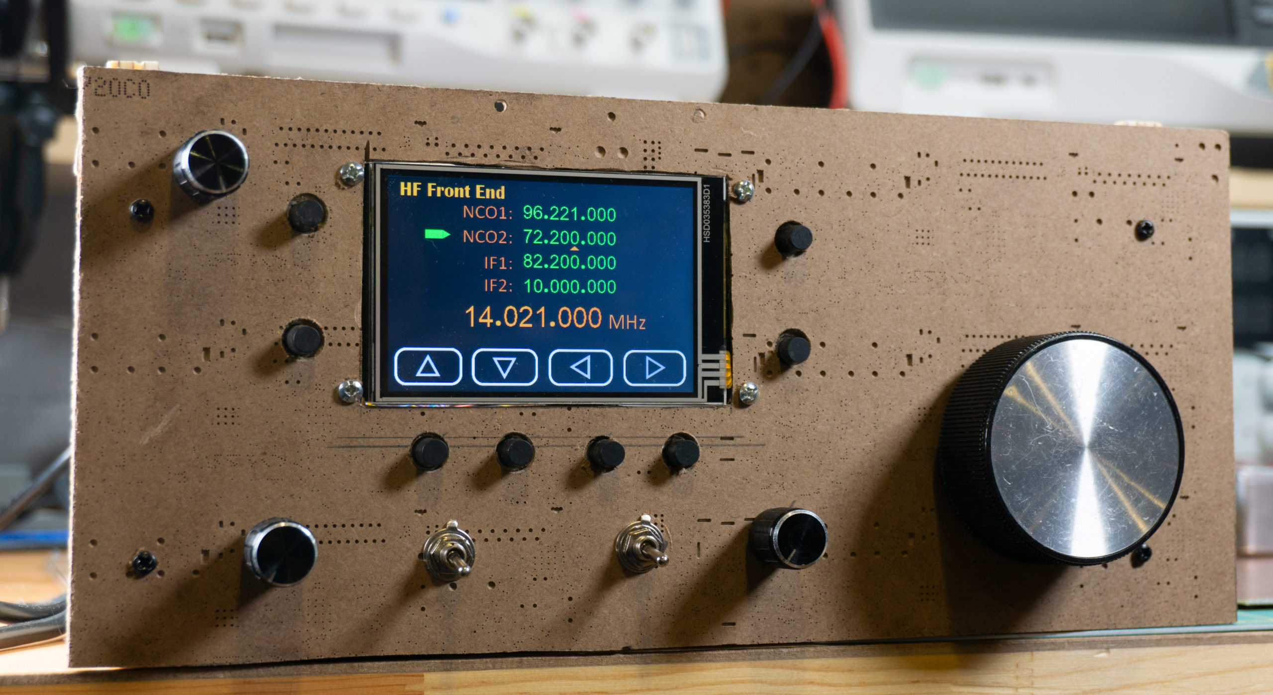
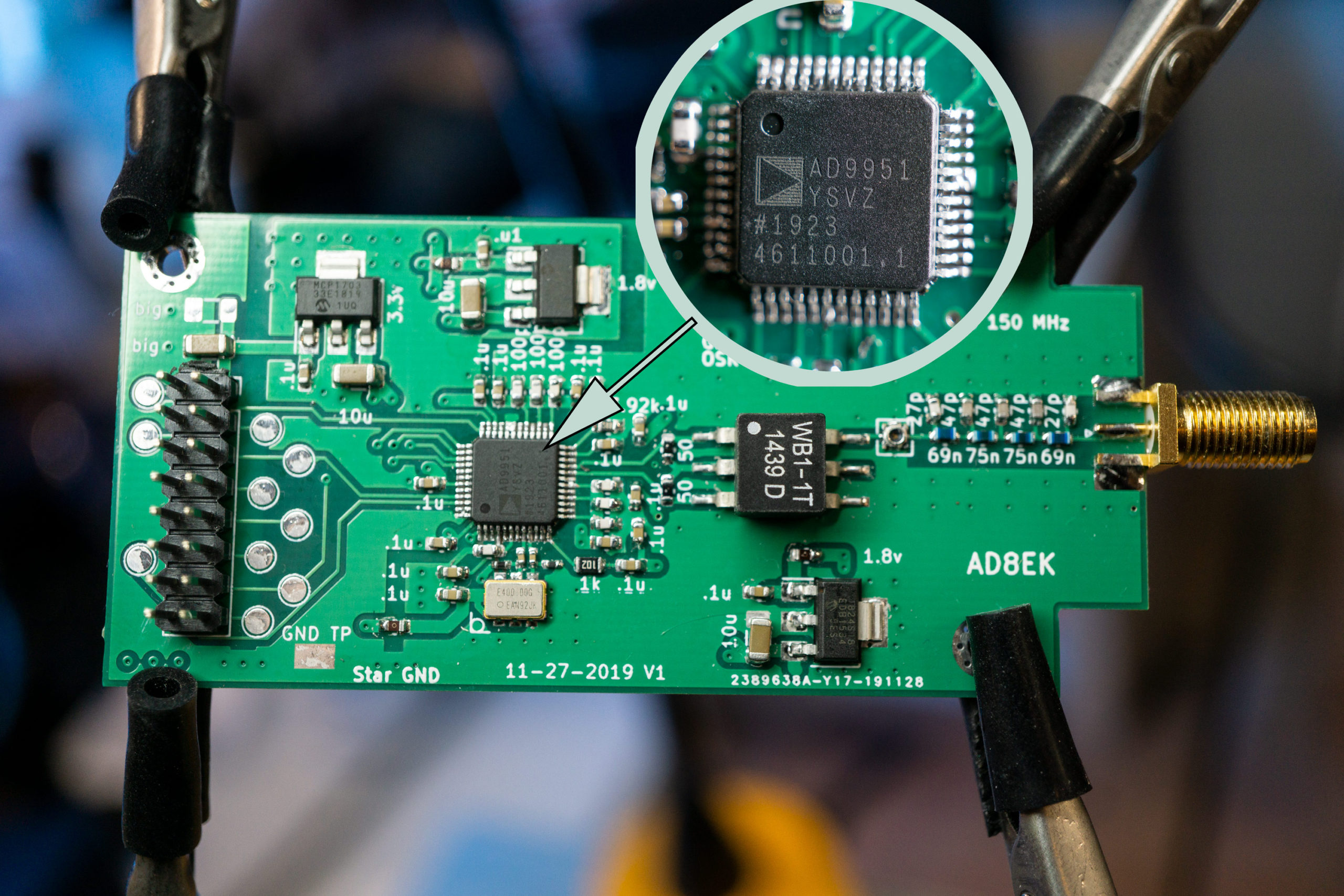
A DDS module I designed and built as a low phase noise RF source for my projects. For my dual conversion receiver I wanted sources with as little phase noise as possible. These AD9951 DDS chips are really nice. I’m clocking the chip with a 400 MHz LVPECL clock, which has reasonably small phase noise but I do think it sets the ultimate noise floor. (I don’t have anything to measure the module to make sure.)

Two modules together inside an aluminum box

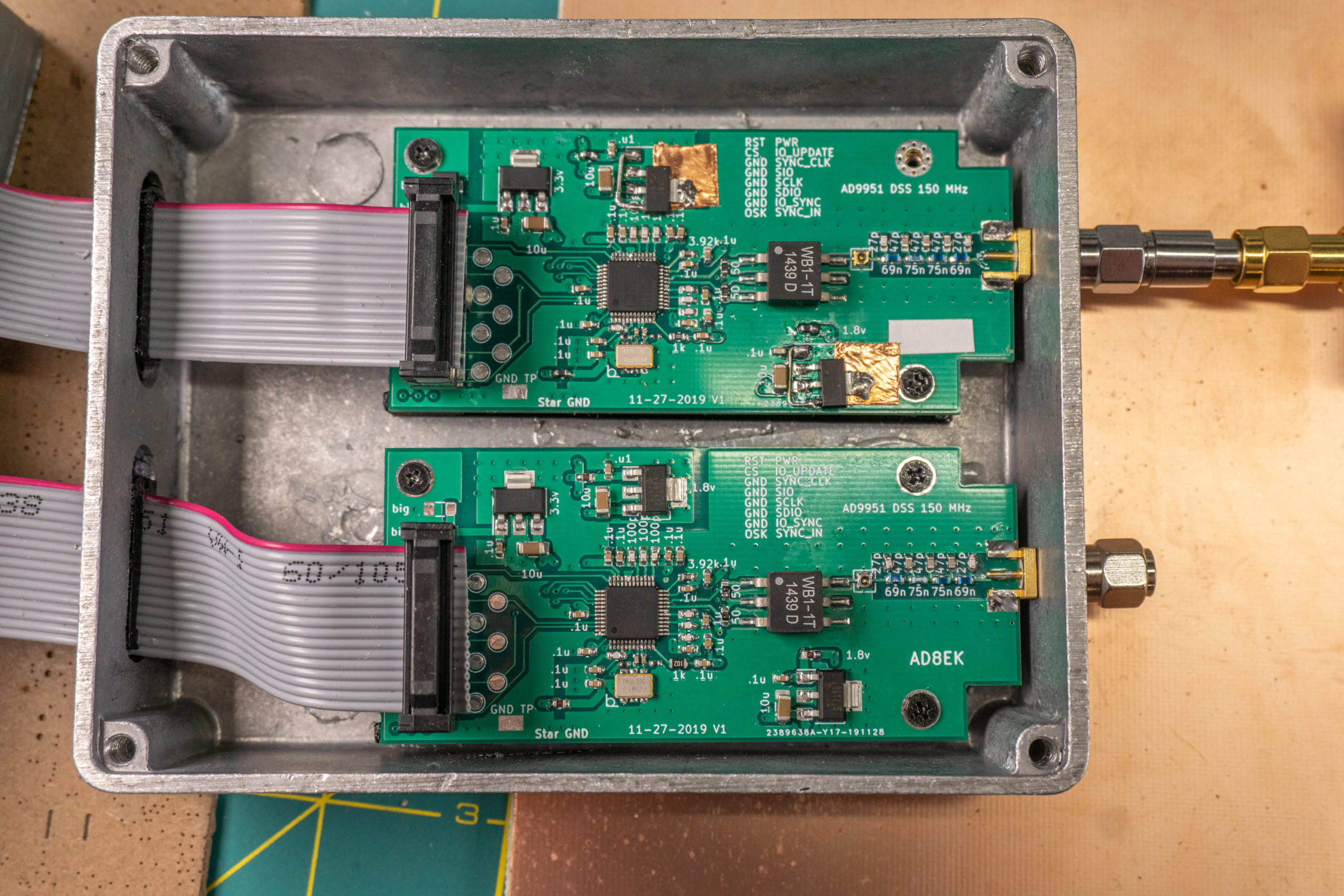
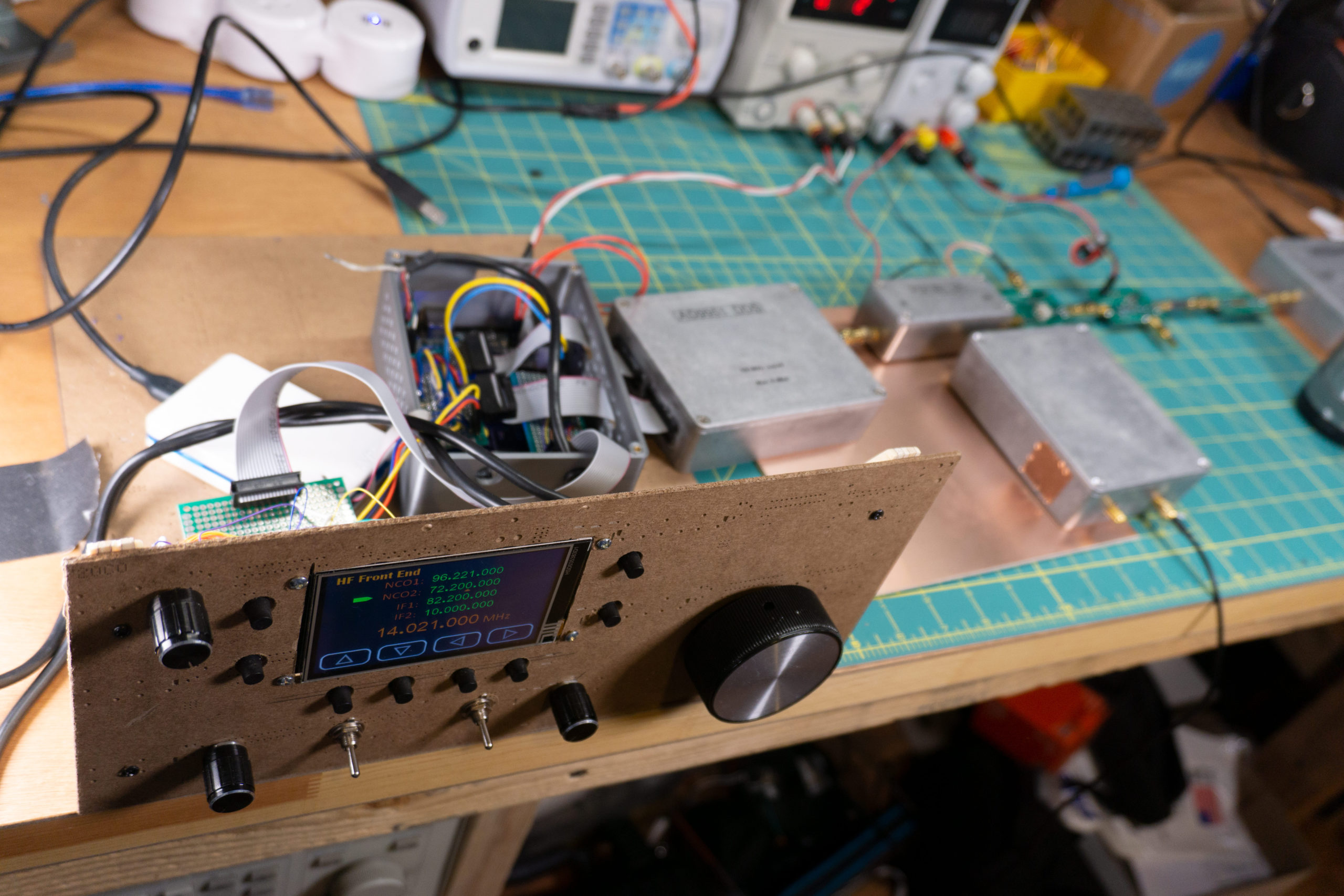
I stuck two of the modules inside an aluminum box I bought off of Amazon, and I control the modules using an SPI port from my processor. The processor is an Atmel SAMS70 (an m7 mobile ARM processor), which is on a board my dad and I have been working on. There would be no problem using Arduino to do the same thing; in fact, I believe there are a couple Arduino libraries out there.

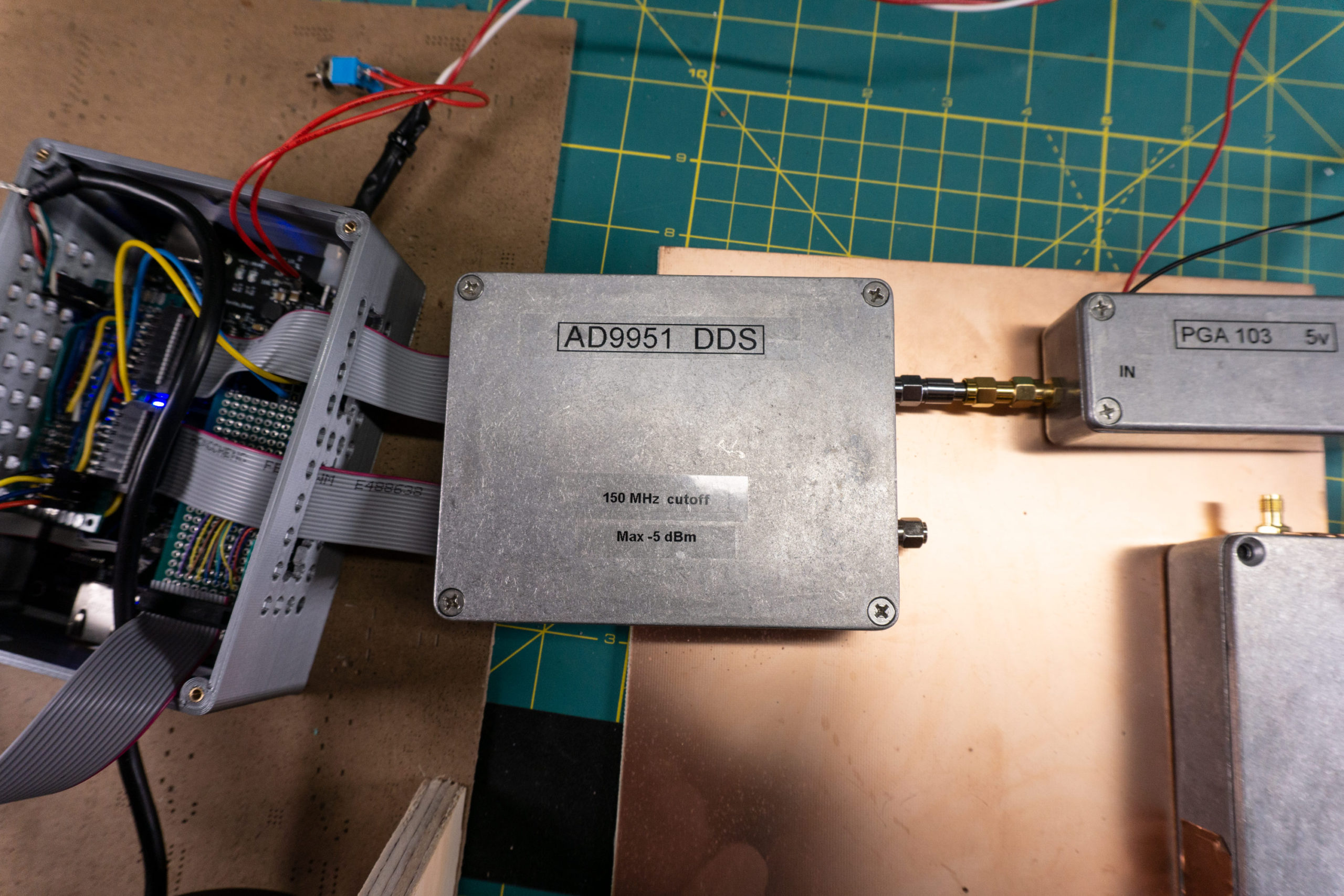
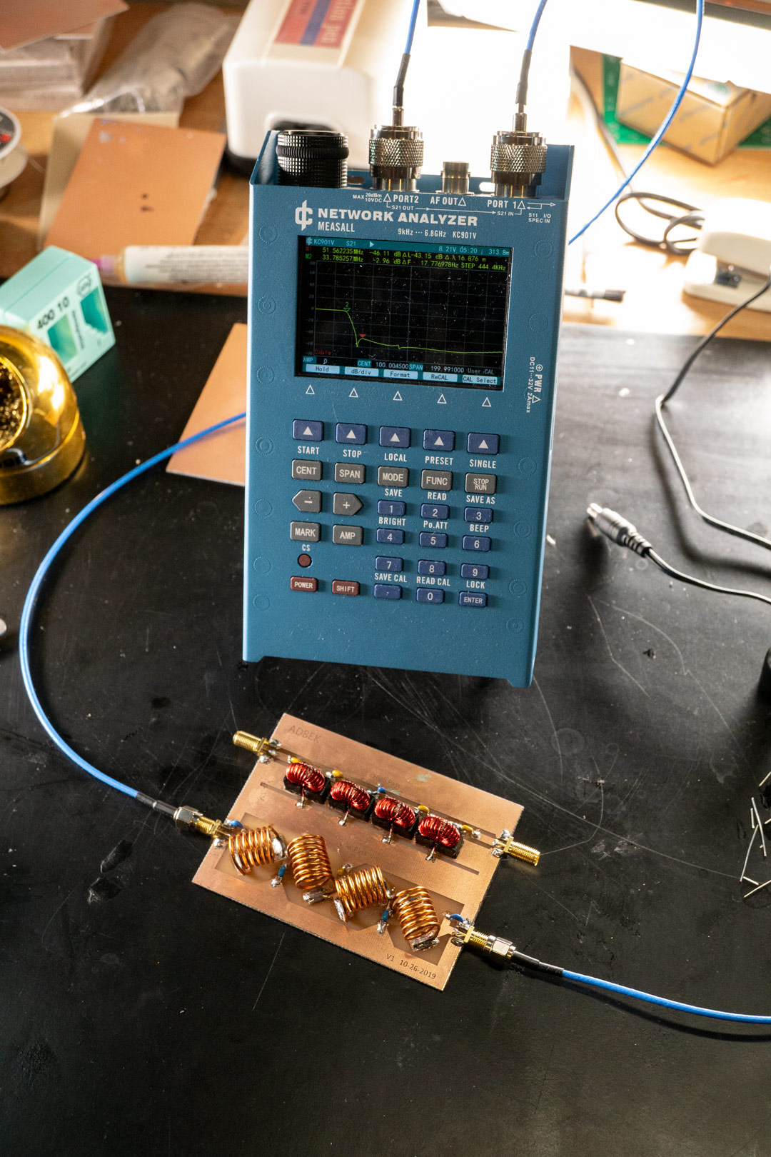
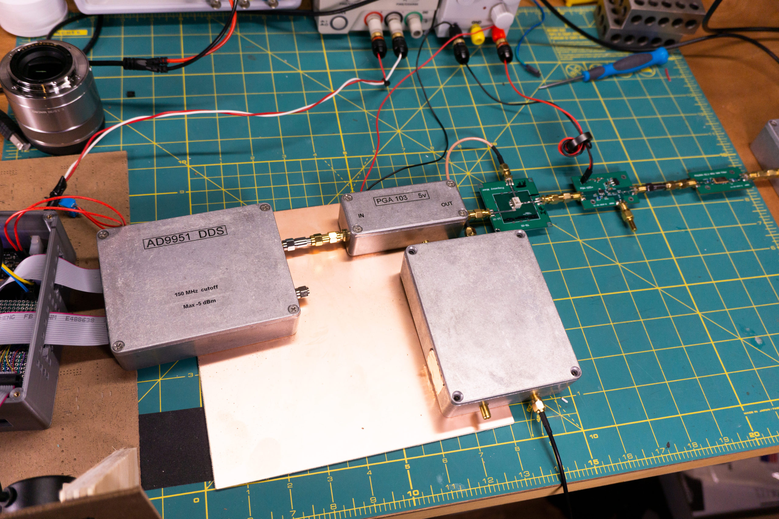
In the picture above you can see the box containing the microcontroller on the left and on the right you can see the DDS feeding an amplifier block. Those aluminum boxes are nice for RF projects.

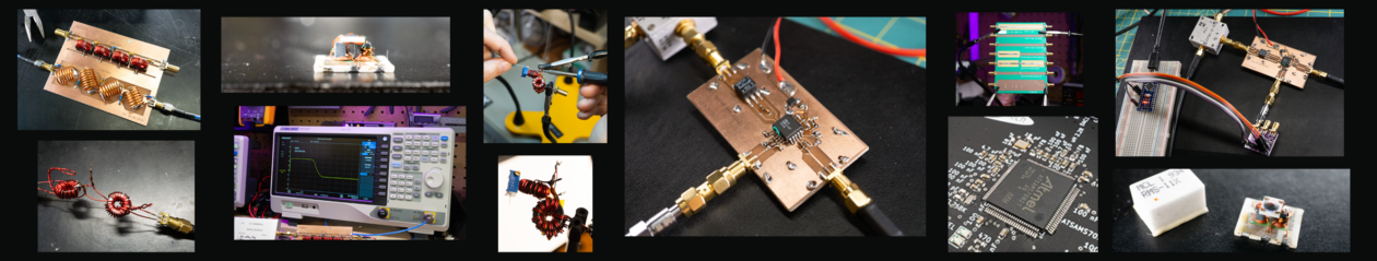
I’m really happy with how these came out, they work great and are easy to use. They are expensive chips though. I think they were around $30 a peace, so my hand was shaking a little when I soldered them on.

As far as design details go, I mostly used the reference design from the datasheet. The LVPECL clock wasn’t in the datasheet, but the voltage was right for providing a strong clocking source (you just need to make sure you bias them properly). The reconstruction filter at the output is a 9th order Chebychev filter with a cutoff at 160 MHz. I probably could have pushed that up a little higher in frequency, but I really only want to use these modules as high as the 2m band so the 160 MHz cutoff is fine.

Facebooktwitterredditpinterestlinkedinmail

KC901V Network Analyzer

KC901V

I’ve had it for about a year now and I can now say I truly love it. It’s from China and I took a real risk in buying it, but the product works great as a hobby VNA.

KC901V display

When I was shopping for a VNA, I spent a lot of time on eBay looking for used VNAs. In my price range I found a lot of old Keysight boxes that work up to 3 GHz. I was very tempted, but when I came across the KC901V I saw I could get a portable VNA that works up to about 7 GHz! I took a chance and bought it.

I have not been disappointed. There are a few quirks, but the interface works great and the metal body makes the whole thing feel solid. Support is good too! I had an issue with saving data to an SD card and e-mailed the guys; they were back to me within an hour and I got it worked out (it was simple and it was my fault).

Also, there is a nice ethernet interface which allows me to control the device from my computer. There is a caveat with it, you can only grab raw data that has not been corrected by calibration. This means you have to write something to do calibration for you. But, after a few hours, I figured out how to get MATLAB talking with the VNA so I can make nice graphs like the one below.

Before you rush to get one, you need to have in mind that the device does not do a full two port measurement. You measure either S11 or S21 at a time. Also, there is a bit of a matching problem when doing S21 measurements. To fix this I put 10 dB pads on both the connectors to get the ringing down. But, once you figure out how to deal with these issues, the unit works great for the price considering it works up to 6.8 GHz.

Facebooktwitterredditpinterestlinkedinmail

Noise Figure of a 2N3904 HF Preamp

I was curious about the noise figure of a standard 2N3904 BJT used in an RF preamp, so I built the circuit shown above. Using my home built NF measurement kit, I found the circuit has a noise figure of about 7.5 dB.

My interest was sparked by a YouTuber I really like named Charlie Morris (ZL2CTM): https://www.youtube.com/channel/UCSNPW3_gzuMJcX_ErBZTv2g. He makes the coolest radios using the construction technique you see in the picture. This is one of his designs for a preamp that works in the HF bands. If you are interested, the design for the circuit can be found here: https://www.youtube.com/watch?v=iRABXFKScqk&t=653s

2N3904 NPN BJT

A couple things to note about the measured 7.5 dB noise figure:

  • No attempt was made to maximize NF in the design. It was simply constructed as a gain block to provide 10 dB of gain and match 50 ohms input and output impedances. The design will work just fine for Charlie’s needs in the 80m and 40m bands.
  • I found a data sheet saying the maximum NF of the 2N3904 is 5 dB. This is consistent with my result, I’m sure the feedback used in the design increases the NF a couple dB.
  • I’m still working out the kinks in my home made noise figure kit. I’m pretty confident right now that my result is correct to within plus or minus 0.5 dB.

Fun afternoon project!

Facebooktwitterredditpinterestlinkedinmail

Home Made HF Radio

HF Radio Front Panel

I’m in route to making my own HF radio for my hobby. I’ve been working on this one for the last few months, and since my brother set me up with a blog, here is my show and tell.

The facade

I just put together this control panel last week. The display is a 3.5″ Nextion (Enhanced I believe), the buttons and rotary encoders are from Amazon, and I bought that large knob on Ebay. Right now the panel just controls a couple of DDSs, which are used as LOs to get into a first and second IF. (Who am I talking to?)

The guts

The individual components are hidden in metal boxes. I hope to take pictures of the insides and put them up here soon.

Hopefully more to come soon!

Facebooktwitterredditpinterestlinkedinmail